This
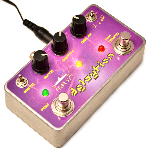
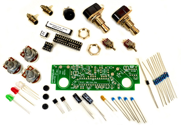
tutorial demonstrates how to build Delaytion™,
PedalSync's analog delay control station, which features tap tempo,
modulation, and four program storage.
Delaytion
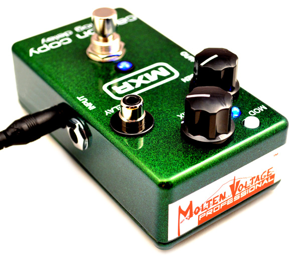
can control most analog delays, including Dunlop's MXR Carbon Copy
delay, Malekko Ekko 616 delay, and Build Your Own Clone's Analog Delay.
If
you would rather not build it, click
here to purchase Delaytion
If
you would rather have Molten Voltage modify your MXR Carbon Copy
for free with purchase of Delaytion or MIDI Delaytion, click here
to send an email for payment and shipping information.
If
you would rather have Molten Voltage modify your Malekko Ekko 616
for $55, click here
to send an email for payment and shipping information.
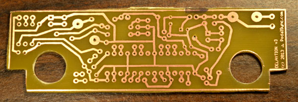
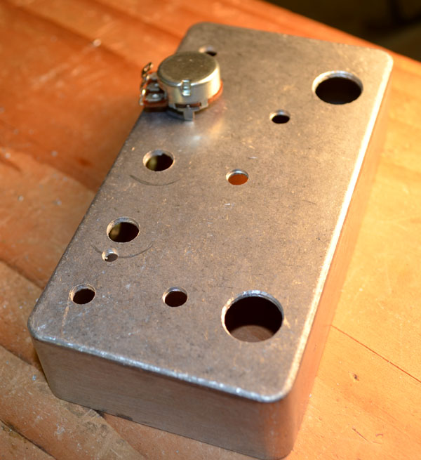
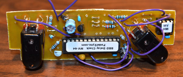
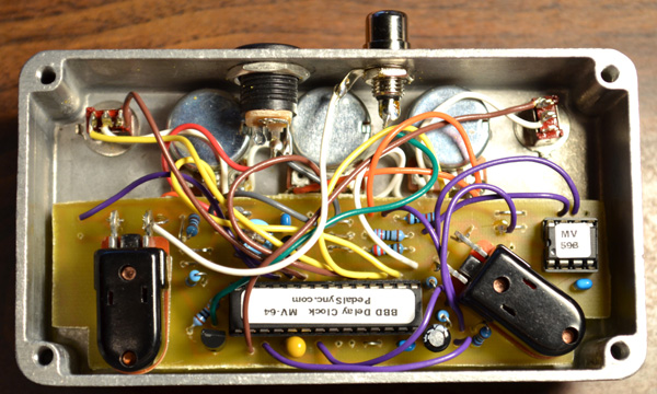
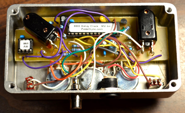
Connect
the nine (9) jumper wires identified in the Layout Diagram (A, B, C,
D, E, F, H, I, J)
(D-D is bare in the photo)
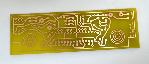
Note that there are no jumpers required if you purchased the printed circuit board.
Ground
the correct pins for chip select (CS1 and CS2 in the Layout Diagram).
For the Carbon Copy, ground CS2. For the BYOC Analog Delay, ground both.
Click
this link
for the Delaytion Schematic which includes a Chip Select table.
Make a
small loop in four pieces of bare hookup wire (about 3/4") and
run those wires through the holes for the button connections from the
back, then solder in place. Clip off the loops.
*
Insert
the pushbutton switches from the top and secure them on the back side
of the circuit board with a double-thick nut. Add an extra regular
nut to obtain the proper spacing of approx. 1/4".
Bend
the switch hookup wires through the pushbutton lug holes (while
clipping the excecss) and solder in place.
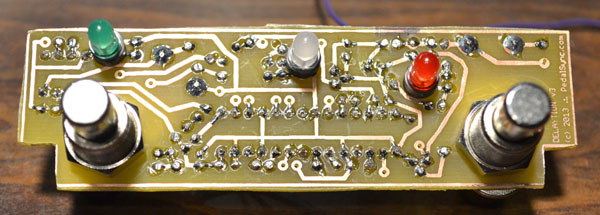
Put
0.12" spacers on the the LEDs, then run the leads through the
holes, noting polarity. Bend the leads back up through the circuit
board and solder on the adjacent pads.
Note that the LEDs are simply soldered to their pads if you purchased the Printed Circuit Board (no adjacent pads).
*
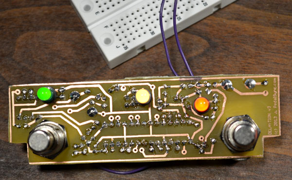
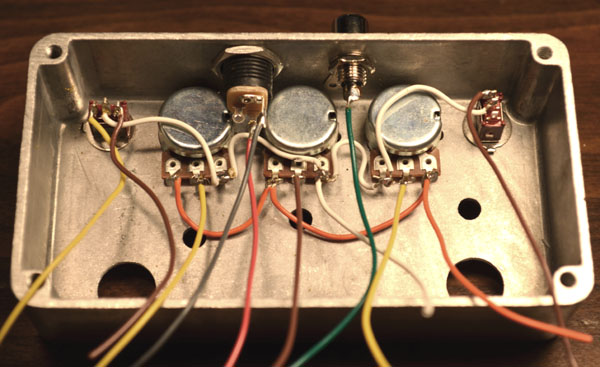
Connect
the two power wires and test the LEDs and pushbuttons before installing.
NOTE:
Delaytion and the Delay must share a common ground, therefore either
connect the ring of the RCA jack to ground on both pedals, or use
a daisy-chain type power connection
*
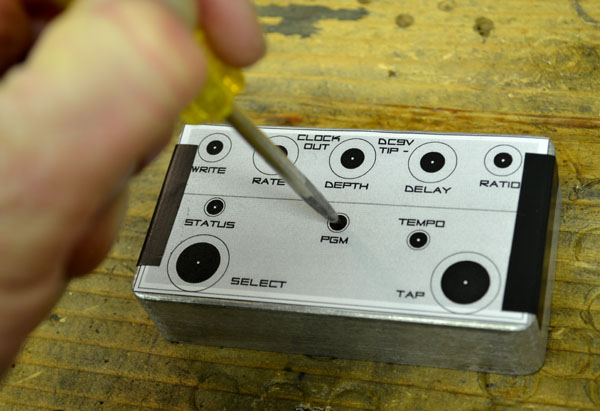
Dress
it up and Turn it on!
*
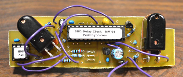
Modify
your Ekko 616 to receive Delaytion's clock signal.
1)
tap tempo timing with 3 delay ratios
2) create and recall four presets
3) no need to open up the pedal to change modulation ratio and depth
4) extended delay time
Disclaimer:
Carbon Copy is a trademark of Dunlop Manufacturing Inc. which is unrelated
to Molten Voltage.
Information
contained in this publication regarding device applications and the like is
provided only for your convenience and may be superseded by updates. It is
your responsibility to ensure that your application meets with your specifications.
MOLTEN VOLTAGE MAKES NO REPRESENTATIONS OR WARRANTIES OF ANY KIND WHETHER
EXPRESS OR IMPLIED, WRITTEN OR ORAL, STATUTORY OR OTHERWISE, RELATED TO THE
INFORMATION, INCLUDING BUT NOT LIMITED TO ITS CONDITION, QUALITY, PERFORMANCE,
MERCHANTABILITY OR FITNESS FOR PURPOSE. Molten Voltage disclaims all liability
arising from this information and its use. No licenses are conveyed, implicitly
or otherwise, under any Molten Voltage intellectual property rights.
PedalSync,
Delaytion, Tru-Foot, ReMute, NODE, Molten Voltage, Visionary Effects, DIGITAL
CONTROL : ANALOG SIGNAL, "Design simple Design sublime", and "the
future just showed up" are all trademarks of Molten Voltage.