 |
|
|
| |
|
|
Key
Features:
Dead
Simple for musicians to use
Low
Cost
State
of the Art Technology
¤
Digital control over your Analog designs
¤ Put your company way ahead of the competition
¤ Consumers will soon expect it
¤ Robust, 128 program storage
¤ MIDI
Compatible and with CV/pulse-dependent
devices
Marketing
+
¤ Easy to create stand-alone pedals
that can be used traditionally and tested in-store
¤ Use PedalSync™
and Tru-Foot™
trademarks on your devices and in advertising
¤ Links to your products from the PedalSync website
Manufacturing
efficiency
¤ Scalable - combine chips like building
blocks to make elaborate designs
¤ Efficiently Designed to ensure Low part count
¤ Thru-Hole or SMT
¤ Wide range of chips with many more coming soon
Security
¤ Much harder to copy your designs
¤ Optional labels specific to your product
Molten
Voltage product support
¤ Development boards available
¤ Low cost customization to meet your specs
|
|
Chips
& Modules:
¤
Master
Controller Module
¤
Analog
BBD Delay Clock Chip and Module
¤
Tru-Foot™
LFO Chips (MIDI, Tap, CV, or Pot control) and Modules
¤
Four
Pots Chips and Modules for 5 or 18-volt digital potentiometers
¤
Relay
Bypass Chips and Modules with ReMute™
technology - logic or pushbutton switch controlled, quiet true-bypass
switching
¤
4
MIDI Presets Chips and Module
¤
Pulse
Output Chip
¤
MIDI
Pulse Chip
¤
Tap/Pulse
Converter Chip
¤
9
Switches Chip and Module
¤
MIDI
Program Change and Bank Select Chip
¤
Voltage
Conversion Module (5v, 9v, 10v, 12v)
¤
One
Trick Pony - Discrete MIDI Data Device
¤
many
more to come!
|
|
|
|
|
|
PedalSync
Master Control Development Board
The
PedalSync Master Control Development Board sends
MIDI Program Change, Clock, and Self-Programming commands to other PedalSync
devices. Master
Controller Datasheet
A
fully-functional Master Control Development Board for the PedalSync
system which includes: large 3-digit display; program select
pot; start/stop, down, up, and tap/save buttons; clock and tempo LEDs;
PCB mounted 5 pin jacks; Master Control chip and all other necessary
components
Available
as a Development Board or with external components allowing
it to be used as the PCB for a name-brand PedalSync controller.
Designed with the End User in mind.
The
Master Control interface has been designed to make switching and
storing programs as simple as possible so the end-user can concentrate
on creativity.
Programs
are selected using the Up and Down buttons or by turning the Program
Select knob. The selected program number is displayed on a large
bright 3-segment LED display. The selected program is engaged by
pressing the Start/Stop button.
Making
all connected PedalSync devices save their current settings is even
easier - simply hold down the Tap/Save button for 2.5 seconds and
BOOM - done!
Tempo Control
The
Master Control interface sends out MIDI Clock data so all sequencing,
oscillating, and repeating PedalSync chips are locked in.
Tempos
can be continually adjusted on-the-fly with the Tap Button, using
the Up and Down buttons, using the potentiometer, or with a pulse
input. An LED indicates the current tempo, allowing users to adjust
the tempo when the clock output is stopped.
The
Master Control chip stores the tempo associated with each of the
128 programs. Alternatively, a program can be made to use the existing
tempo for when multiple programs are used in a single song.
Backwards-compatible with MIDI
The
PedalSync Master Controller sends out standard MIDI Start, Stop,
and Clock messages as well as Song Select and Program Change messages
on Channel 15.
As
a result, the PedalSync Master Control chip can synchronize an entire
rig of MIDI-enabled rack effects, pedals, modular synths, and amplifiers.
Two
Display Options
There
are two versions of the Master Control available.
MV-58
displays programs 1-128 sequentially. MV-58B displays 16
Banks of 8 Programs each.
Version MV-58B can be controlled by MIDI Bank Select and Program
Change chip MV-65, shown below. MV-65 is the brain for an
external controller with Bank Up and Down and 8 Program switches,
more familiar to some musicians.
|
|
Master
Control Development Board
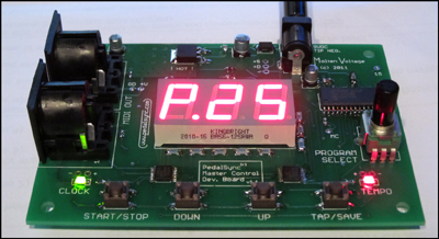
Master
Control Dev. Board - Assembled
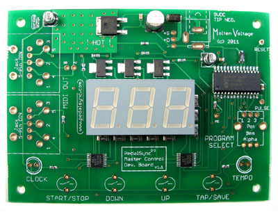
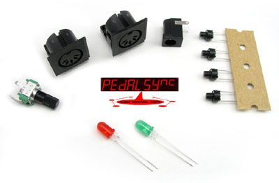
Master
Control Dev. Board - Components
|
| |
|
|
|
PedalSync
Analog BBD Delay Clock chip MV-64
The
PedalSync BBD Delay Clock chip MV-64 outputs the high-speed
digital clock required by classic Panasonic MN3205 and MN3208 Analog
Delay ICs and their clones.
MV-64
outputs a clean, variable, high-speed clock designed to drive Bucket
Brigade Delay chips, and stores and recalls Delay Time, Delay Ratio,
Clock/Tap Status, Modulation Ratio or Rate, Depth, Offset, and Bypass
Status. Analog
BBD Delay Clock Datasheet
MV-64
features:
Tap,
Pot, MIDI Clock, and CV timing
The delay time can be set using 4 different methods. The program default
is Pot/Tap, allowing stand-alone effects that do not require an external
clock signal. MV-64 also works well in modular
synth designs that rely upon a control voltage.
Delay
Ratios
Four separate delay ratios: 1:1 (quarter note), 3:4 (dotted
eighth), 2:3 (quarter note triplet), and 1:3 (eighth note triplet)
can be selected.
Modulation Ratio / Rate
The Modulation Pot Input can perform two different functions.
The
Ratio Pot multiplies or divides the delay modulation speed
relative to the delay time based on musical subdivisions: two whole
notes; whole note; half note; half note triplet; quarter note (tap
speed); quarter note triplet; 8th note; 8th note triplet; 16th note.
As a result, synchronized devices can oscillate at different yet
complimentary rates.
The
Rate Pot allows the modulation rate to be set manually and
independent of any timing source.
Depth
The Depth pot adjusts the depth of the modulation sweep with a maximum
of +/- 50% of the delay time.
Offset
The Offset pot adjusts the modulation waveform timing against the
incoming clock with up to 360 degrees of phase shift. The modulated
delay sweep can accent, syncopate, push the beat, or get right in
the pocket.
128
Program Storage
Up to 128 programs can be stored by toggling a switch or upon a command
from the PedalSync Master Controller. Programs are recalled using
the PedalSync Master Controller, standard MIDI Program Change messages
on Channel 15, or the PedalSync 4 Presets chip (MV-59).
Configurable
for 1-4 BBD chips
MV-64 can be used with 4 different pin-selectable BBD chip configurations.
|
|
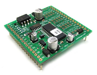
Analog
BBD Delay Clock chip
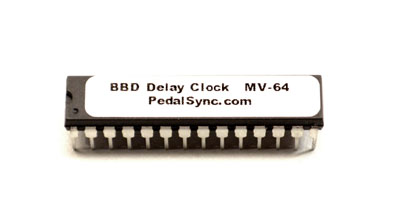
MV-64
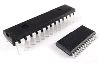
Thru-hole
or SMT
DIGITAL
CONTROL : ANALOG SIGNAL™
|
PedalSync
BBD Delay Clock Module
The
PedalSync BBD Delay Clock Module (MV-64) provides the
circuitry necessary to quickly prototype your latest designs or use
as a plug-and-play BBD clock generator. This compact (1.6 x 1.7")
module features 2x 15-pin 0.1" pitch headers set 1.5" apart.
Input Voltage = +9VDC.
A
6N138 optocoupler and 74F14 Schmitt Trigger handle all the incoming
PedalSync and MIDI messages. Two separate voltage regulators and three
separate grounds combined with careful PCB design optimize separation
between 5 volt, 3.3 volt, and Analog circuits for very low noise operation.
The
BBD Delay Clock Module also provides two buffered outputs for PedalSync
or MIDI thru.
|
|
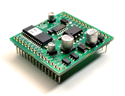
BBD
Delay Clock Module
|
|
|
|
|
|
PedalSync
Tru-Foot™ LFO chips MV-55 and
MV-55B
The
PedalSync Tru-Foot™ LFO chips MV-55 and MV-55B
output an ultra-clean analog (16-bit DAC) waveform, and store and recall
Waveform, Clock/Tap Status, Speed, Ratio, Offset, Duty Cycle, and Bypass
Status. MIDI, Tap, Pulse, and Pot control are all possible. Featuring
real-time control of potentiometers without large waveform spikes. Tru-Foot
LFO Datasheet
Waveform
Users select Sine, Square, Triangle, or Tru-Foot™. With the Duty
Cycle pot, the Triangle waveform can be transformed into a sawtooth
up or down.
The
Tru-Foot™
waveform realistically emulates the feel of
a foot rhythmically controlling a wah-type pedal.
It is particularly effective with voltage-controlled filter designs.
Clock or Pot/Tap timing
The LFO timing source is selected with a momentary switch. The program
default is Pot, allowing stand-alone effects that do not require an
external clock signal.
Speed
The Speed pot adjusts the base LFO rate between 24 and 240 bpm. This
range can be further adjusted using the Ratio control from 3 bpm to
960 bpm.
Ratio
The Ratio pot multiplies or divides the LFO speed relative to the
incoming clock based on musical subdivisions: two whole notes; whole
note; half note; half note triplet; quarter note (tap speed); quarter
note triplet; 8th note; 8th note triplet; 16th note. As a result,
synchronized devices can oscillate at different yet complimentary
rates.
Offset
The Offset pot adjusts the waveform against the incoming clock with
up to 360 degrees of phase shift. The LFO can accent, syncopate, push
the beat, or get right in the pocket.
Duty Cycle
The Duty Cycle pot adjusts the relative playback speed of the first
and second half of the waveform to make the output swing. The thirteen
duty cycle ratios correspond to the most common musical subdivisions:
1/20; 1/8; 1/6; 1/4; 1/3; 3/8; 1/2; 5/8; 2/3; 3/4; 5/6; 7/8; 19/20.
Five Simultaneous Outputs
Tru-Foot™
LFO chip programs are stored by toggling a switch or upon a command
from the PedalSync Master Controller.
Programs
are recalled using the PedalSync Master Controller, standard MIDI
Program Change messages on Channel 15, or the PedalSync 4 Presets
chip (MV-59).
Extensive
smoothing and interpolation algorithms provide seamless transitions
between programs and allow real-time control.
MV-55
loads program 1 automatically on startup, while MV-55B reads
the potentiometers and switches on startup.
|
|

Exclusive
Tru-Foot™ LFO Technology
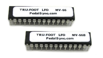
MV-55
and MV-55B
|
PedalSync
Tru-Foot™ LFO Module
The
PedalSync Tru-Foot LFO Module (available as MV-55 or MV-55B)
provides the circuitry necessary to quickly prototype your latest
designs or use as a plug-and-play LFO generator. This compact (1.6
x 1.7") module features 2x 15-pin 0.1" pitch headers set
1.5" apart. Input Voltage = +9VDC.
A
6N138 optocoupler and 74F14 Schmitt Trigger handle all the incoming
PedalSync and MIDI messages. Two separate voltage regulators and three
separate grounds combined with careful PCB design optimize separation
between 5 volt, 3.3 volt, and Analog circuits for very low noise operation.
The
Tru-Foot LFO Module also provides two buffered outputs for PedalSync
or MIDI thru.
|
|
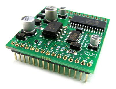
Tru-Foot™
LFO Module
|
|
PedalSync
Voltage Conversion Module
The
PedalSync Voltage Conversion Module (VCM) converts
the limited LFO output from the
PedalSync Tru-Foot LFO chips (MV-55 and MV-55B) and their modules to
one of four
output voltage ranges: 0-5v, 9v, 10v, or 12v
The
module also features Depth and Center control connections for maximum
waveform flexibility.
The
VCM has been designed to maximize voltage output range and can be
used with either standard LM358 op amps or Rail-to-Rail op amps for
full voltage swing.
See
the Voltage
Conversion Module Datasheet
for more information.
|
|
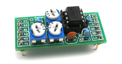
Voltage
Conversion Module (VCM)
|
| |
|
|
|
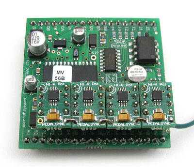
PedalSync
Four Pots chips MV-56 and MV-56B
The
PedalSync Four Pots chips MV-56
and MV-56B store and recall up to four potentiometer settings
for 128 different programs. Four
Pots Datasheet
The
MV-56 chip sends real-time or programmed resistance data to
low cost Microchip digital potentiometers (MCP4151) which generate
analog resistances.
The
MV-56B chip sends real-time or programmed resistance data to
PedalSync Hi-V Pot modules.
In
addition to the pot settings, the chip also stores the Bypass
status and two (2) more user defined momentary switch inputs and pin
outputs that can control other device features like alternate signal
paths or PedalSync Relay Bypass MV-57 modules. The Bypass
status is indicated by an LED which controls our Relay Bypass chip.
Four
Pots chip programs are stored by toggling a switch or upon a command
from the PedalSync Master Control chip.
Programs
are recalled using the PedalSync Master Controller, standard MIDI
Program Change messages on Channel 15, or the PedalSync 4 Presets
chip (MV-59).
|
|
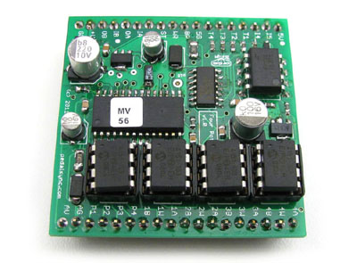
Four
Pots chips
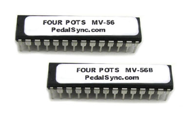
MV-56
and MV-56B
|
PedalSync
Four Pots Module
The
PedalSync Four Pots Module (available as MV-56 or MV-56B)
provides the circuitry necessary to quickly prototype your latest
designs or use as a plug-and-play module. This compact (1.9 x 1.9")
module features 2x 18-pin 0.1" pitch headers set 1.7" apart.
Input Voltage = +9VDC.
The
chip receives input from traditional analog (5K) potentiometers,
then sends real-time or programmed resistance data to digital potentiometers
which generate analog resistances.
As
a result, the user interface is instantly recognizable and intuitive,
yet highly sophisticated.
A
6N138 optocoupler and 74F14 Schmitt Trigger handle all the incoming
PedalSync and MIDI messages. Two separate voltage regulators and
three separate grounds combined with careful PCB design optimize
separation between 5 volt, 3.3 volt, and Analog circuits for very
low noise operation.
The
Four Pots Module also provides four buffered outputs for PedalSync
or MIDI thru.
PedalSync
Hi-V Pot and Microchip MCP4151 digipots available separately.
Four
Pots Module
MV-56B with Hi-V Pot Modules
|
|
Four
Pots Module
Four
Pots Module
MV-56 with MCP4151 Digipots
|
|
PedalSync
Hi-V Pot Module
The
PedalSync Hi-V Pot Module
is a programmable replacement for analog potentiometers,
and is designed for applications requiring higher current and voltages
than standard 5-volt digital potentiometers can handle.
The
module offers extended 18-volt and 5 mA power limits,
yet fits in standard 10-pin DIP socket (8 pins used on the MV-56B
module).
The
Hi-V Pot module is designed for use with the PedalSync MV-56B Four Pots
Module but can be used as a stand-alone part.
See
the Hi-V
Pot Module Datasheet
for more information.
|
|
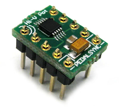
Hi-V
Pot Module
|
| |
|
|
|
PedalSync
Relay Bypass Chips (MV-57
and MV-57B)
PedalSync
Relay Bypass chip MV-57 receives a signal from other PedalSync
chips or a 3.3 or 5-volt logic source and silently switches a relay
in response. Relay Bypass chip MV-57B
is controlled via a momentary switch, allowing true bypass designs without
the big blue switch.
A DPDT
latching relay (Panasonic TQ2-L-5V) connects directly to the chip.
Two status LEDs also connect to the chip indicating whether or not
the relay is in bypass mode.
ReMute™
Technology
An optical MOSFET circuit mutes the output signal to virtually eliminate
switching noise without degrading the audio signal.
The
Relay Bypass chips also feature a light show and automatic relay reset
on startup.
See
the Relay
Bypass Datasheet for more information.
|
|
Relay
Bypass chips
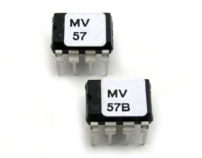
MV-57
and MV-57B
|
|
PedalSync
MV-57 Logic-Controlled Relay Bypass Module with Jacks
The
PedalSync Relay Bypass Module for MV-57 is designed for control
by an external logic source input, such as the ones provided by the
PedalSync 9 Switches, Tru-Foot LFO, Four Pots, Pulse Output, or Analog
BBD Delay Clock chips.
The
Relay Bypass Module is ideal for effect, pedalboard, or loop box designs.
For
stereo applications, one signal can control two modules.
This compact (1.85 x 1.8") module features PCB-mounted jacks,
easy header connections, and ReMute™
technology.
The
headers provide connections for power input, audio signals, momentary
switch, and two optional LEDs. The module also features sockets
for the chip and relay.
Who
wouldn't want to store and recall the bypass status for up to 128
setups?
See
the Relay
Bypass Datasheet for more information.
|
|
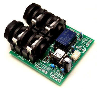
Logic-Controlled
Relay Bypass Module with Jacks
|
| |
|
|
|
PedalSync
MV-57B Pushbutton Switch Relay Bypass Module
The
PedalSync Relay Bypass Module for MV-57B is designed to sit in
a 9-volt battery compartment and connect to a 9-volt power supply, allowing
easy, quiet, true-bypass retrofitting of your vintage effects.
The
Relay Bypass Module is also ideal for effect, pedalboard, or loop
box designs.
For
stereo applications, a single momentary switch can operate two modules.
This compact (.85 x 1.7") module features 2x 5-pin 0.1"
pitch headers set 1.3" apart, and ReMute™
technology.
The
headers provide connections for power input, audio signals, momentary
switch, and two optional LEDs. The module also includes sockets for
the chip and relay.
Input
Voltage = 7-30VDC.
See
the Relay
Bypass Datasheet for more information.
Check
out this tutorial
to see how to turn your wah pedal into a Rooster-Wah where
you can leave it cocked at a particular angle.
|
|
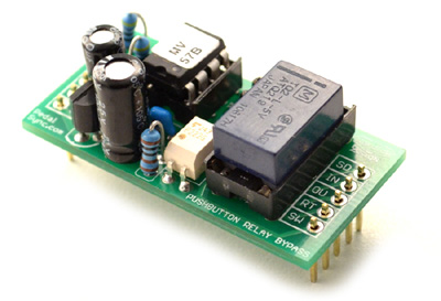
Pushbutton
Switch Relay Bypass Module
|
|
|
|
|
|
PedalSync
4 Presets chips MV-59 and MV-59B
The
PedalSync 4 Presets chips MV-59 and MV-59B
sequentially send MIDI Program Change messages 1-4 on Channel 15 each
time a momentary switch is pressed, and feature a power-on light show.
If the
device is designed for dual-use (PedalSync and Stand-Alone),
a custom latching network interrupts and overrides any other incoming
control signal, giving the 4 Presets signal priority.
Because
all the primary PedalSync chips can be programmed separately (without
the Master Controller), users can switch their stand-alone device
to one of four presets, adjust their settings, and program those settings
by toggling the Program switch.
3
different LED indicator options are available from the same chip.
Custom
programming is also available.
See
the 4
Presets Datasheet for more information.
|
|
4
Presets chips
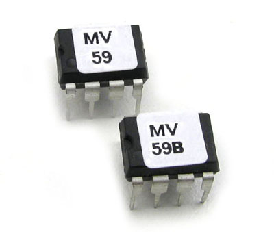
MV-59
and MV-59B
|
PedalSync
4 Presets Module
The
PedalSync 4 Presets Module Module for MV-59 and MV-59B
is designed for applications where 4 PedalSync or MIDI programs need
to be recalled and connects easily to the Tru-Foot™
LFO Four Pots, and 9 Switches modules as well as the other PedalSync
28-pin chips.
This compact (1.1 x 1.2") module features 2x 6-pin 0.1"
pitch headers set 1" apart.
The
headers provide connections for power input, MIDI In and Out, optional
LEDs, and momentary switch.
Input
Voltage = 5VDC filtered.
See
the 4
Presets Datasheet for more information.
|
|
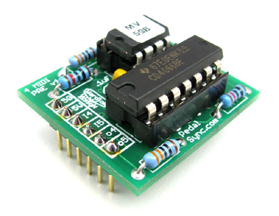
4
Presets
Module
|
|
|
|
|
|
PedalSync
Pulse Output chip MV-60
The
PedalSync Pulse Output chip MV-60 sends
two independent pulse outputs synchronized to the incoming clock, taps,
or control voltage (CV), and stores and recalls each output's Ratio,
Offset, and Bypass Status.
see
Tru-Foot LFO, above, for a description of the Ratio and Offset controls
The
Pulse Output chip is designed to control modular synth sequencing
designs as well as BOSS™ effects that accept a pulse input
such as the PH-3 Phase Shifter, AW-3 Dynamic Wah, and the DD-7 Delay.
Any other device that allows a pulse timing input can be similarly
controlled.
See
the Pulse
Output Datasheet for more information.
|
|
Pulse
Output chip
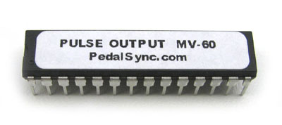
MV-60
Thru-hole
or SMT
|
| |
|
|
PedalSync
MIDI Pulse chip MV-61
The
PedalSync MIDI Pulse chip MV-61
sends a MIDI tempo signal compatible with most popular Line 6™
MIDI devices. The output is synchronized to the incoming clock. The
chip stores and recalls the Ratio, Offset, and Bypass Status.
see
Tru-Foot LFO, above, for a description of the Ratio and Offset controls
See the MIDI Pulse Datasheet for more information.
|
|
MIDI
Pulse chip
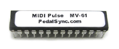
MV-61
|
| |
|
|
PedalSync 9 Switches chip MV-62
The
PedalSync 9 Switches chip MV-62 is
designed for pedalboard switching controls using the extremely quiet
PedalSync MV-57 Relay Bypass system.
MV-62
works well with any other application where up to 9 separate momentary
switches control the logic state of 9 separate outputs and the on/off
states must be stored and recalled.
Because
these chips can be combined like building blocks, there exists no
limit on the size of your design.
See
the 9
Switches Datasheet for more information.
|
|
9
Switches chip
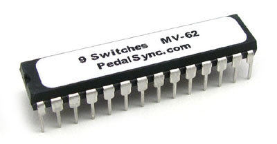
MV-62
|
|
PedalSync
9 Switches Module
The
PedalSync 9 Switches Module
offers an easy way to build programmable pedalboards by synchronizing
9 MV-57 Relay Bypass modules to a central controller which can store
and recall 128 programs based on PedalSync or MIDI data.
In addition
to the 9 switch inputs and corresponding logic outputs, the module
also features all necessary circuitry to read MIDI In, as well as
4 MIDI Thru outputs.
Power,
Status LED and Program Write Switch connections are also provided.
Header
pads are spaced at 0.1", complementing the use of header pins
and wiring harnesses.
#4
screw holes provide a convenient way to attach the module to standoffs
or an enclosure.
The
9 Switches Module can also be used in any application where up to
nine logic outputs need to be stored and recalled.
See
the 9
Switches Datasheet for more information.
|
|
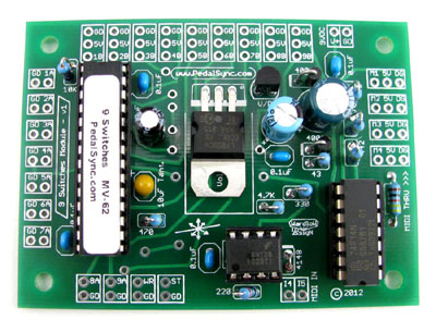
9
Switches
Module
|
| |
|
|
PedalSync MIDI Program Change and Bank Select chip MV-65
The
PedalSync MIDI Program Change and Bank Select chip MV-65 is
designed to add additional functionality to the PedalSync Master
Control Dev. Board (MV-58B), by providing the brains for an external
controller which uses discrete switches for bank up/down and for each
program.
This
type of controller and the Bank/Program style display is more familiar
to some musicians.
See
the MIDI
Bank Select Datasheet for more information.
|
|
MIDI
Program Change and Bank Select chip
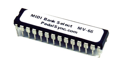
MV-65
|
| |
|
|
PedalSync
Tap/Pulse Converter chip MV-52B
The
PedalSync Tap/Pulse Converter chip MV-52B
allows you to connect a sophisticated, compact, and highly accurate
Tap Tempo controller to your circuit with a minimum of external components.
The
Tap/Pulse Converter chip MV-52B was designed primarily to provide
precision tap input timing control for chips and circuits that have
pulse-activated triggers or external clock inputs, such as sequencers
and timers.
MV-52B
may just as easily be used as a pulse converter, as it provides five
(5) simultaneous pulse outputs syncrhonized to the incoming control
voltage (CV).
See
the Tap/Pulse
Converter Datasheet for more information.
|
|
Tap/Pulse
Converter chip
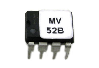
MV-52B
|
| |
|
|
| |
|
Downloads:
PedalSync
CadSoft Eagle™
Module Footprint Library
Right
click link
and save
|
| |
|
|
Follow
Molten Voltage on Facebook for PedalSync updates:
Molten
Voltage

.:.
Member
of NAMM (National Association of Music Merchants)
|
|
Available at:
 Small
Bear Electronics Small
Bear Electronics
or contact
us directly at
questions@MoltenVoltage.com
|